

A heat exchanger’s cooling performance depends not only on its geometry, but on how fluid moves through it and transfers heat. Computational fluid dynamics cooling uses numerical simulations to model fluid flow and heat transfer, revealing how velocity, temperature, pressure, and flow rate vary across a system. These results help engineers assess cooling behavior and compare design choices before building physical prototypes.
It’s natural to focus on an exchanger’s size or rated duty, but uneven flow and local hot spots can also affect thermal performance. This article explains computational fluid dynamics cooling, how CFD models represent flow and heat transfer, and how engineers interpret simulation results. It then applies these principles to heat exchanger design, showing how CFD can compare configurations and inform decisions about geometry and flow distribution.
Key Takeaways
- CFD models how fluid moves and how heat transfers, helping engineers examine temperature, pressure, velocity, and flow rate across a system.
- Simulation results can reveal uneven flow, thermal hotspots, and cooling constraints that may be difficult to assess from overall system ratings alone.
- Model quality depends on how accurately geometry, mesh, boundary conditions, material properties, and solver assumptions represent the real system.
- Engineers can use CFD to compare heat exchanger configurations and understand how design choices affect flow distribution and thermal performance.
- Use simulation findings to guide design decisions, while interpreting the results in the context of the system’s operating conditions and requirements.
Temperature, pressure, velocity, and flow-rate analysis
Computational fluid dynamics cooling analysis calculates how fluid flow affects temperature, pressure, velocity and flow rate. Engineers use these results to identify cooling constraints and understand heat transfer across equipment.
Thermal Analysis for Heat Transfer
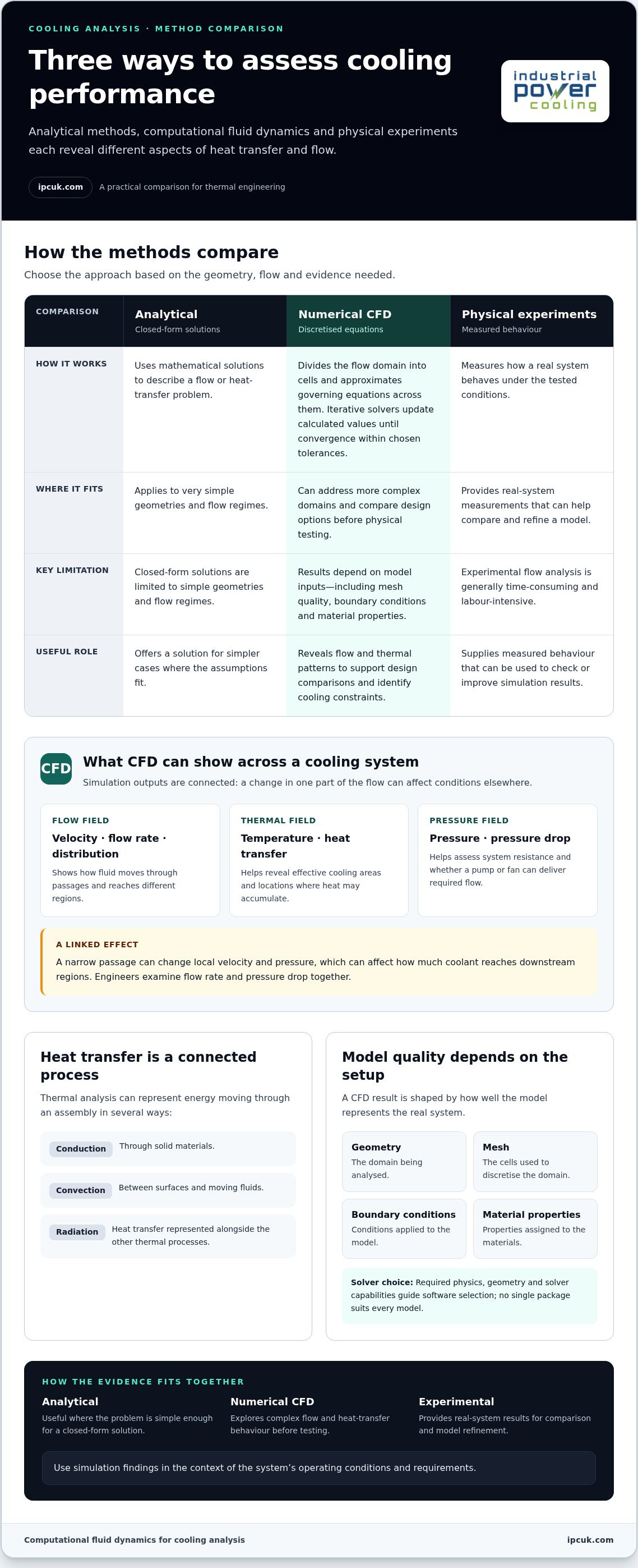
Thermal analysis uses CFD to model heat transfer between fluids, solids and their surroundings. Temperature patterns show where cooling is effective and where heat may accumulate. A model can account for conduction through solid materials, convection between surfaces and moving fluids, and radiation. Together, these processes describe how thermal energy moves through an assembly rather than treating its parts in isolation.
Numerical Analysis and Iterative Solvers
Numerical analysis divides the flow domain into cells and approximates the governing equations across them. The finite volume method uses small control volumes; finite element and finite difference methods offer other ways to discretise the domain. Iterative solvers repeatedly update calculated values until the equations converge within chosen tolerances. Mesh quality, boundary conditions and material properties all affect the result, so engineers review these inputs when a solution behaves unexpectedly.
CFD Software for Cooling Analysis
Thermal and cooling analysis uses CFD software configured to solve fluid-flow and energy equations. No single package suits every model: the required physics, geometry and solver capabilities guide the choice. Software must represent the relevant boundary conditions and material properties, then produce results such as temperature and pressure fields. In practice, engineers select a CFD solver to suit the cooling problem rather than rely on one universal program.
For fluid flow, simulations can calculate velocity distribution, density, temperature, pressure drop, flow rate and fluid distribution. These outputs are connected: a narrow passage can alter local velocity and pressure, affecting how much coolant reaches downstream regions. In a pipe, engineers examine friction, pressure drop and flow rate together. They can also assess whether a pump or fan can deliver the required flow against system resistance.
Analytical, numerical and experimental methods offer different ways to examine performance. Closed-form analytical solutions apply only to very simple geometries and flow regimes. Numerical CFD can address more complex domains by solving discretised equations, while physical experiments measure real system behaviour. Since experimental flow analysis is generally time-consuming and labour-intensive, simulations can help assess design options before testing. Available analytical or experimental results can also help compare and refine a model.
Electronics cooling is one practical application. A model of an enclosure with limited airflow can compare component placement and identify hot spots on circuit boards or near heat sinks. Engineers can assess how fan position changes air distribution and heat removal. The resulting temperature map helps distinguish an isolated hot region from a wider airflow problem, informing adjustments to the layout or cooling conditions.
CFD applications in thermal management and cooling
CFD supports thermal engineering by showing how heat loads, fluid properties and operating conditions affect cooling performance. Applications range from electronics and electric motors to vehicle batteries and industrial equipment.
Thermal Design Considerations
Thermal design balances heat generation, material properties, ambient conditions and practical operating constraints. Cooling must remove the required thermal energy while accounting for trade-offs in noise, reliability and cost. Engineers use CFD to compare natural and forced convection, then assess how each approach handles the system’s heat load. A model can also represent different ambient temperatures and operating conditions.
For printed circuit boards, CFD can model heat transfer among components, board materials and surrounding air. A board carrying power modules, processors or GPUs may generate heat unevenly, so simulation can show how component placement affects local temperatures. Engineers can compare airflow paths and heat-sink arrangements, then assess whether fan placement directs air towards concentrated heat sources. This supports layout decisions before a physical prototype is built.
Altitude changes the surrounding air conditions represented in a thermal model. At higher elevations, lower air density can affect air-side heat transfer and the cooling available from a fan-driven system. Engineers can model the operating environment and compare component temperatures across conditions. A design that relies on air cooling may respond differently from one using a liquid coolant loop, so both the cooling method and the environment matter.
Thermal Management Systems
A thermal management system moves heat away from components and transfers it to the surrounding environment or another working fluid. The complete path, from heat source through cooling surfaces to the final heat sink, determines system behaviour. CFD can assess flow distribution through passages and compare cooling performance under different heat loads. In a coolant manifold, differently sized orifices can balance flow among devices with varying requirements.
CFD has applications beyond electronics, including electric-motor cooling, electric-vehicle battery behaviour, and thermal conditions in vehicle engines or cabins. For each case, engineers define the heat load and ambient conditions, then assess fluid distribution and component temperatures. Simulations can also help determine whether passive airflow is sufficient or forced circulation is needed to transfer the required thermal energy.
For industrial projects, relating simulated operating conditions to the equipment and cooling arrangement helps turn thermal analysis into design decisions. Explore industrial cooling system design in the context of the system’s heat load, fluid path, and operating environment.
CFD simulation of fluid flow and heat transfer
A CFD simulation combines fluid-motion and energy calculations to predict how heat moves through a system. Its value is in connecting flow paths with thermal behaviour, including heat transfer between moving fluids and solid components.
The model starts with a defined flow domain, such as a channel, enclosure or heat exchanger passage. Engineers create a mesh of cells, assign material properties, and specify boundary and initial conditions. These conditions describe inputs such as fluid properties, inlet flow and surface temperatures. The solver then calculates how the system responds within the defined physical domain.
Conjugate Heat Transfer in Solids and Fluids
Conjugate heat transfer models conduction through solids alongside convection between solid surfaces and moving fluids. Both processes act together to determine a cooling component’s temperature. For example, heat can conduct through a metal wall before being carried away by flowing coolant. Modelling the wall and coolant as coupled regions helps reveal where thermal resistance or uneven flow limits heat removal.
At the core, CFD solves conservation equations for mass, momentum, and energy. The National Aeronautics and Space Administration describes the Navier-Stokes equations as governing fluid motion. In a thermal model, the energy equation tracks temperature changes as fluid moves and interacts with surrounding materials. Together, the equations help represent pressure, velocity, and heat transfer across the modeled domain.
Fluid Flow and Heat-Transfer Applications
Fluid-flow and heat-transfer models examine how moving air or liquid carries energy through equipment. This matters in systems where geometry directs flow around components. In an electronics enclosure, for instance, airflow patterns affect heat removal from circuit boards and heat sinks. In a pipe, simulation can show how coolant distribution and pressure loss influence heat transfer along the flow path.
Engineers use CFD for thermal management in electronics, automotive systems and industrial equipment. A model can examine air circulation around components or liquid flow through cooling passages. Boundary conditions represent the operating scenario, while material properties determine how solids and fluids conduct and carry heat. Changing one condition at a time helps reveal whether a thermal issue comes from the heat load, flow arrangement or material response.
Heat Transfer and Thermodynamics
Thermodynamics describes changes in energy and temperature, while heat transfer examines how thermal energy moves between regions. A cooling model needs to account for both the energy balance and the mechanisms of transfer. For example, heat generated in a solid component must pass through its surface and enter the surrounding fluid. The energy equation tracks this exchange across the modelled system.
Results depend on how closely the simulation represents the physical setup. Mesh resolution affects how well the model captures narrow passages and temperature gradients, while boundary conditions define the operating environment. Engineers compare calculated flow and temperature patterns with available analytical or experimental results, then refine the model if needed. This process connects numerical predictions to practical decisions about cooling performance.
Interpreting simulation results
CFD results are useful when engineers relate calculated flow and temperature fields to operating requirements. A colour contour alone cannot establish whether a cooling design performs adequately.
Cooling simulations require equipment geometry, fluid properties, material data, heat loads and boundary conditions. They also need a suitable mesh and sufficient computing resources. Hardware demand depends on mesh size, solver and whether the analysis is steady-state or time-resolved. GPU acceleration is useful when the selected software and solver support it.
Engineers interpret results by checking whether the model represents the physical system and whether its outputs answer the design question. Temperature contours can locate a hot spot, while velocity vectors reveal recirculation or poorly supplied regions. Pressure distribution helps explain flow resistance. For a fan-cooled enclosure, the analysis should show whether air reaches the heat-generating components, not merely whether the average enclosure temperature seems acceptable.
Numerical convergence is one part of this assessment. Iterative solvers update values for the governing equations until the solution meets its convergence criteria. Engineers can review residual trends alongside design-relevant quantities such as outlet temperature or pressure drop. If those quantities continue to change materially as the calculation proceeds, the result needs further investigation before it informs a decision.
Model assumptions matter too. Turbulence treatment, boundary conditions, geometry simplification and mesh resolution can all affect predicted flow. An aerodynamics model, for instance, may need to represent flow separation around a surface; a cooling model may instead focus on air distribution through narrow passages. Poor assumptions can produce confident but incorrect results, so engineers compare predictions with available analytical or experimental data and refine the model where needed.
Early thermal simulation helps teams assess performance before building physical prototypes. During development, engineers can compare component locations, airflow paths or heat-load scenarios, then use the findings to guide design changes. This can reduce the number of prototypes needed for design verification. The benefit is greatest when the model addresses a clear decision, such as whether a proposed layout directs sufficient cooling flow towards a heat-generating component.
GPU acceleration can shorten calculations suited to parallel processing, but it cannot replace sound modelling. Practical resource requirements depend on the case: a steady model with a manageable mesh differs from a time-resolved model that captures changing turbulence. Engineers assess model size, solver capability, memory needs and required detail together, then judge results against system requirements rather than relying on visual output alone.
Heat exchanger design
Heat exchanger design balances heat transfer against fluid-side pressure drop and flow distribution. CFD helps engineers assess these interacting effects across the exchanger geometry, rather than judging a design by surface area alone. The key question is whether the chosen arrangement transfers the required heat while distributing fluid through the available passages.
A model represents the exchanger’s flow passages, separating surfaces and operating conditions. Engineers can compare channel geometry, inlet and outlet arrangements, and flow paths to see how each affects fluid movement. Low-velocity areas may indicate uneven distribution, while high resistance can increase pressure drop. These patterns help explain how design choices affect thermal performance across the exchanger.
CFD is especially useful for comparing alternatives before building a physical prototype. Engineers can evaluate multiple design configurations, varying geometry or operating conditions while keeping other model inputs consistent. This helps identify which changes improve heat transfer and which create unwanted flow resistance. The analysis can also narrow down the options for further physical testing.
For example, a proposed passage arrangement may direct more fluid through one region than another. Simulation results can show the resulting velocity distribution and temperature field, helping engineers assess whether the full heat-transfer surface is being used effectively. If flow is poorly distributed, revisions can focus on the responsible geometry or inlet arrangement rather than unrelated components.
Model quality remains central to design decisions. Geometry simplification must preserve features that influence flow, while boundary conditions should represent the intended operating scenario. Mesh resolution needs to capture relevant passages and gradients. Engineers interpret outputs together, including temperature, flow rate and pressure drop, because a thermal gain considered on its own may hide its effect on overall system operation.
CFD software supports comparative analysis, but the method does not replace engineering judgement. The useful result is a reasoned comparison tied to design requirements, not simply a detailed visualisation. Engineers can use simulation findings to refine a configuration, assess trade-offs and decide which concepts merit prototype evaluation. This approach can reduce the number of physical prototypes needed during product development.
For heat exchanger projects, connect the simulation objective to the exchanger’s operating conditions and design constraints. Discuss your heat exchanger design requirements as part of that assessment.
Industrial Power Cooling (IPC): Dry Coolers
Industrial Power Cooling (IPC) offers dry coolers for industrial applications where heat must transfer from a process fluid to ambient air. CFD analysis can help assess how airflow and heat transfer affect cooling performance, while equipment selection depends on the application and its operating requirements.
For projects requiring a different cooling arrangement, IPC also offers chillers, cooling skids and charge air coolers. These equipment types address distinct system needs, so thermal analysis can help clarify the duty and flow conditions that shape equipment decisions. Simulation findings provide useful engineering context when planning a new system or reviewing an existing one.
For a discussion about industrial cooling equipment and project requirements, contact Industrial Power Cooling (IPC) or visit ipcuk.com.
Turn simulation findings into a practical next step
The next step is to turn model outputs into requirements that guide equipment decisions. Define the operating conditions and cooling duty, then relate them to the design priorities that matter in operation. This makes computational fluid dynamics cooling part of a wider engineering decision, not an isolated simulation exercise.
Industrial Power Cooling (IPC) offers dry coolers, chillers and cooling skids for industrial applications. The right equipment category depends on the process and its requirements, so a clear specification helps focus the discussion. Consider how the proposed system fits the wider installation and operating context before settling on a configuration.
For a practical discussion of industrial cooling equipment, explore options with Industrial Power Cooling (IPC). A defined set of project requirements provides a sound starting point for the next engineering conversation.
Frequently Asked Questions
What is Computational Fluid Dynamics?
Computational Fluid Dynamics, or CFD, is a numerical method for examining fluid motion and its interaction with surrounding surfaces. It can also track dispersed particles carried by a moving fluid, including how drag and dispersion affect their paths. This is useful when a design question concerns more than average flow, such as where particles travel or collect within a process stream.
How Should a Beginner or Decision-Maker Approach CFD?
Start by defining the engineering decision the model must support, such as comparing operating conditions or locating a thermal constraint. Then identify the outputs needed to make that decision and the inputs required to represent the system. This scope helps a decision-maker assess whether the model is relevant, while a beginner can learn what each input and result means before reviewing visual plots.
What Are the Benefits of Using CFD in Engineering?
CFD lets engineers examine conditions that are difficult to observe throughout an operating system, including internal flow distribution and local thermal behaviour. This can support decisions about whether a fan or pump can overcome system resistance and deliver the required flow. It also gives project teams a consistent basis for comparing design alternatives, provided each case uses suitable assumptions and comparable operating conditions.
What Are the Limitations, Risks, and Common Mistakes in CFD?
A CFD result can look precise while representing the wrong physical situation. Common risks include oversimplified geometry, unsuitable boundary conditions or assumptions that fail to represent the actual flow regime. A converged calculation alone does not prove that the model is valid. Engineers should distinguish numerical convergence from physical accuracy, then compare predictions with relevant measurements or established analytical results where available.
What Trends Are Shaping the Future of CFD?
High-performance computing continues to expand the scale of CFD problems engineers can address, enabling more detailed and time-dependent analyses. Another important direction is multiphysics modelling, which can examine interacting effects such as fluid flow, heat transfer and structural deformation. These methods help represent connected system behaviour, although each added physical interaction also requires suitable model inputs and engineering interpretation.
What Is Computational Fluid Dynamics (CFD) Cooling Analysis?
Computational fluid dynamics cooling analysis applies CFD to assess how a cooling system moves fluid and transfers heat under defined operating conditions. It can help determine whether a component receives adequate cooling or whether system resistance affects fluid delivery. The analysis is most useful when its purpose is clear, such as examining a design change or comparing expected operation under different heat loads.
How Is CFD Used to Design and Optimize Cooling Systems?
Engineers use CFD to compare design alternatives against the same operating requirements, then assess which changes improve the selected performance measures. For example, a project team might compare a proposed flow arrangement with an alternative, reviewing heat removal alongside pressure loss. This helps identify trade-offs and prioritise design revisions before physical evaluation.


