

The most compact cooling package isn’t necessarily the right fit for a process. Industrial cooling skids bring selected equipment together, but their suitability depends on how the package connects to site utilities, process pipework and control systems.
A packaged system can provide a defined assembly, but it won’t resolve every site constraint or interface by itself. Before comparing proposals, establish what the skid includes, what sits within the wider installation and who is responsible for each connection. These details help determine whether the proposed system can meet the process requirements and integrate with the site.
This guide explains what a cooling skid can include and how to compare packaged and site-assembled approaches on the same basis. It also covers the process and site information needed to define cooling duties, operating conditions, interfaces, controls and maintenance access before procurement. A clear technical brief makes proposals easier to assess and helps prevent responsibilities from falling between the skid and the site installation. For bespoke projects, coordinating design, manufacture and pipework installation can bring these requirements together.
Key Takeaways
- Use industrial cooling skids to bring selected equipment into a coordinated package, and define clearly where the skid scope ends.
- Map the cooling duty from process heat input to heat rejection, recognising that the flow path depends on the application and engineered configuration.
- Compare packaged and site-assembled options across integration, site work, flexibility, access and project coordination.
- Build the specification from process-fluid details, operating conditions, heat load and expected operating range, then document site interfaces.
- Coordinate design, manufacture, pipework installation and ongoing support early so the skid fits site conditions throughout the project lifecycle.
What Is an Industrial Cooling Skid, and What Problem Does It Solve?
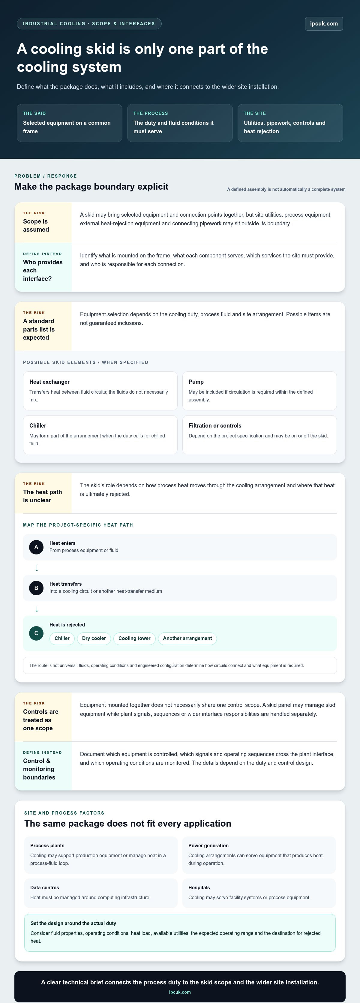
An industrial cooling skid is a project-specific assembly of selected cooling equipment mounted on a common frame to manage heat removal or process-fluid cooling. It brings defined parts of a cooling arrangement together so they can be engineered and installed as a coordinated package. Industrial cooling skids can organise equipment and connection points, but a skid is not automatically a complete, self-contained cooling system.
The frame supports the equipment included in the agreed scope. Depending on the design, this can help define the installation area and make the relationship between components easier to plan. It doesn’t remove the need to engineer connections to the wider facility. Site utilities, the process equipment being cooled, external heat-rejection equipment and connecting pipework may sit outside the skid boundary. Define the scope and interfaces clearly to establish who is responsible for each connection and how it will be coordinated.
What equipment can an industrial cooling skid bring together?
Equipment selection follows the cooling duty, process fluid and site arrangement, rather than a standard package list. A skid might include a heat exchanger to transfer heat between fluid circuits, and a pump if circulation is required within the defined assembly. A chiller may form part of an arrangement when the duty calls for chilled fluid; What is a Chiller? provides background on chiller function and applications. Other possible elements, such as filtration or controls, depend on the project specification and may be located on or off the skid.
These are possible roles, not guaranteed inclusions. The specification should identify which equipment is supplied on the frame, what each component serves and which connections or services the site must provide. This makes the package easier to assess against the process requirements.
Where are industrial cooling skids used?
Cooling skids are used in facilities where heat must be removed from a process or fluid circuit, but the duty varies by setting. In process plants, cooling may support production equipment or manage heat in a process-fluid loop. In power generation, cooling arrangements can serve equipment that produces heat during operation. Data centres need heat managed around computing infrastructure, while hospitals may need cooling for facility systems or process equipment.
These applications don’t share one standard design. Fluid properties, operating conditions, heat load, available utilities and the destination for rejected heat all influence the arrangement. A skid suited to one duty may not suit another without project-specific engineering. Define the package boundary alongside the process and site interfaces to determine what the skid should do and what the wider installation must provide.
How an Industrial Cooling Skid Works Within a Larger System
A cooling skid performs a defined part of a wider heat-management process. Heat enters through the process equipment or fluid, transfers into a cooling circuit, and is then carried to a selected heat-rejection method. Depending on the design, that destination could be a chiller, dry cooler, cooling tower or another arrangement. The route is project-specific: the fluids, operating conditions and engineered configuration determine how the circuits connect and what equipment is required.
A cooling skid operates as part of a larger system, so its performance depends on coordinated process, cooling and control interfaces. Assess its function in relation to the equipment it serves and the site services that support it.
How heat transfer and fluid circulation fit together
Heat transfer moves energy from a warmer process stream to a cooler fluid or another heat-transfer medium. A heat exchanger can transfer heat between circuits without the fluids necessarily mixing. For example, a process circuit may give up heat across an exchanger to a separate cooling-water circuit. This is an example, not a standard arrangement for every skid.
Circulation moves fluid through the relevant parts of the system. A pump may be included where the engineered arrangement requires one, while other designs may rely on equipment or circulation outside the skid boundary. Distinguish the process-side conditions, such as fluid type and required operating range, from the cooling circuit’s requirements and the site connections serving each circuit. This helps define which flow paths the skid manages and which connections must be made during installation.
What controls and monitoring contribute
Where included in the specification, controls can coordinate equipment within the defined design. The control boundary matters: a skid control panel may manage skid equipment, while signals, operating sequences or responsibilities at the wider plant interface may be handled separately. Project documents should make these divisions clear rather than assuming that equipment mounted together shares a single control scope.
Where specified, monitoring can show relevant operating conditions and help operators understand how the system is functioning. Which parameters are monitored and how the system responds depend on the duty and control design. For broader engineering context, ASHRAE Standards for Industrial Cooling offers a reference point for industry resources. Project requirements still need to be established for the system and site.
For a practical specification, map the process inlet and outlet, the skid’s cooling-circuit connections, required utilities, and any control or monitoring interfaces. Mark each connection as part of the skid or supplied by the site. This interface schedule gives design and installation teams a shared basis for coordinating pipework and responsibilities. Where these boundaries need to be developed alongside a bespoke system, cooling system design and integration can form part of the project scope.
Packaged Cooling Skid or Site-Assembled System: What Should You Compare?
A packaged skid and a site-assembled system are different ways to deliver and integrate cooling equipment. A skid groups selected equipment on a frame, while a site-assembled arrangement brings components together at the facility. Neither approach is automatically preferable. Compare both against the same project requirements, including duty, location, interfaces and scope. Packaging alone doesn’t determine installation effort or suitability.
Packaging may simplify selected installation tasks by bringing equipment together before delivery, but it doesn’t remove the need for site engineering. Both approaches need a defined scope for utilities, process connections, pipework, lifting and access. Compare what each proposal includes and excludes, and account for how equipment will be installed, operated, maintained and replaced. This makes responsibilities visible before they affect project planning.
When a packaged industrial cooling skid may fit
A packaged approach may suit a project where selected equipment can be coordinated on a frame and the site connections are understood early. Check whether the completed assembly can be transported along the required route, positioned in the available space and accessed for installation and maintenance. Delivery constraints, lifting arrangements and connection locations are project-specific. A compact package won’t help if it cannot be placed or serviced as planned.
When a site-assembled arrangement may be considered
Existing plant layouts or staged works may influence whether components are installed separately at the facility. This approach may allow the installation sequence to reflect site constraints, but access for assembly, maintenance and eventual equipment replacement still needs planning. Compare those requirements with the space and handling needs of a packaged assembly. The preferred solution depends on the cooling duty, location, interfaces and agreed project scope, not a general rule about which method is better.
How to Specify an Industrial Cooling Skid for Your Project
A project-specific specification starts with the cooling duty, then translates operating needs into equipment requirements and defined site interfaces. The core inputs for specifying industrial cooling skids are process-fluid details, flow and temperature conditions, heat load, expected operating range, available utilities, space and access constraints, and connection requirements. Providing these together gives the design team a consistent basis for developing and assessing the proposed arrangement.
Define the process duty and operating conditions
Begin with the heat that must be removed and the conditions under which the process operates. Design decisions depend on more than a single target temperature: the expected operating range and changes in process demand can affect the arrangement. Use project data rather than assumed default values, and identify which figures are measured, estimated or still subject to engineering verification.
- Describe the process fluid. Record its identity and any relevant properties or operating constraints that may affect material selection or heat transfer.
- Document flow and temperatures. Provide the required flow conditions and inlet and outlet temperatures for the process circuit. Distinguish normal operation from other expected operating states.
- Define the heat load. State the heat-removal duty and explain how it was determined. Include variations in demand if the process operates under more than one condition.
- Set the operating envelope. Record expected operating ranges, duty cycles and any process limitations the cooling arrangement must accommodate. Have estimated or preliminary figures reviewed during engineering development.
- Identify the heat-rejection arrangement. Describe the intended site arrangement or available cooling services so the cooling circuit can be considered in context, rather than specified as an isolated package.
Document site interfaces and lifecycle requirements
Once the duty is clear, describe the conditions the equipment must meet at the facility. Site information can affect the skid layout, connection positions and division of work between the package and installation. Include available utilities, proposed pipework routes, connection points, usable footprint, access for delivery and installation, and any operating constraints around the installation area.
- Mark the process-side and cooling-side connections, including their locations and the scope boundary for each.
- Record the available utilities and relevant connection requirements, along with constraints that may affect installation sequencing.
- Allow space and access for operation, inspection, maintenance and removal or replacement of equipment.
- Identify control interfaces and responsibilities where these form part of the project requirements.
Include lifecycle requirements in the specification, not as an afterthought. Consider how operators will reach equipment and how planned maintenance can be carried out within the available space. A layout that fits the installation area but restricts routine access may create avoidable operational difficulties. Clear drawings and an interface schedule can help align the skid design with industrial cooling system pipework installation and site conditions.
Industrial Power Cooling manages bespoke cooling projects from conceptual design through manufacture and installation. Discuss your cooling skid requirements to establish a project-specific basis for design and site integration.
From Cooling Skid Design to Installation and Ongoing Support
Industrial cooling skids need to be considered across the project lifecycle, not only as equipment to be manufactured and delivered. Requirements, engineering, manufacture, site installation and operational support are connected stages. Coordinating them early helps align the skid’s defined scope with pipework, access and site conditions, reducing the risk of interfaces being left unresolved between project phases.
What to expect across project delivery
Industrial Power Cooling designs, manufactures and installs bespoke industrial cooling systems, including cooling skids. Its project work can extend from conceptual design through manufacture and installation, with the scope shaped around project requirements. Process duties and site information inform the initial design; as engineering develops, the package boundary and connection responsibilities can be coordinated with the wider installation.
Pipework is a key part of this coordination. Routes, connection positions and the relationship between the skid and existing plant can affect installation. Considering industrial cooling system pipework alongside the equipment brings these interfaces into the project plan rather than leaving them as a separate task.
- Establish requirements. Define the cooling duty, operating conditions, site constraints and scope boundaries.
- Develop the engineering. Translate project inputs into a bespoke system design and identify relevant interfaces.
- Manufacture the system. Build the agreed cooling equipment and assembly to the project design.
- Coordinate installation. Plan the skid’s position, connections and related pipework around site conditions.
- Plan operational support. Consider access, maintenance needs and how the wider cooling system will be looked after after installation.
Define installation and commissioning responsibilities, technical documentation and handover requirements for each project rather than assuming they are identical across systems. A clear scope aligns the work and makes responsibilities at each stage easier to understand.
Plan for maintenance after installation
Consider maintenance access while developing the layout. Allow space and practical access to inspect, service or remove equipment, and consider how the system can be maintained within the facility’s operating constraints. These decisions connect the initial design to the longer-term use of the cooling system.
Industrial Power Cooling provides maintenance and repair services for cooling towers and cooling units, supporting clients globally. Bringing lifecycle requirements into early project discussions keeps operational needs in view alongside manufacture and installation, without assuming every system requires the same maintenance approach.
For a project that needs coordinated design, manufacture and site installation, discuss your cooling skid requirements with Industrial Power Cooling.
Move Your Cooling Skid Project Forward
Turn project assumptions into a shared engineering basis. Bring together the process information, operating constraints and site details that will shape the design, and identify any items that still need investigation. A clear brief gives procurement and engineering teams a stronger starting point for evaluating options and coordinating the package with the wider installation.
With over 20 years of experience, IPC designs, manufactures and installs bespoke industrial cooling systems. This project capability supports a coordinated approach from early design decisions through site integration, with the system tailored to the requirements established for the application.
Discuss your project scope, process needs and site conditions with IPC. Discuss your industrial cooling skid requirements with IPC, and take the next step towards a well-defined industrial cooling skids specification.
Frequently Asked Questions
What is an industrial cooling skid?
An industrial cooling skid is a framed assembly that brings selected cooling equipment together for a defined industrial duty. The skid describes an equipment arrangement, not necessarily a complete cooling installation. It may form one part of a plant system, with process equipment, heat rejection, utilities or connecting pipework beyond its boundary. The specification should distinguish the supplied assembly from the systems it connects to.
How does a cooling skid work?
A cooling skid supports heat removal by moving heat from a process or fluid circuit towards a suitable heat-rejection arrangement. In a design using a heat exchanger, heat passes between fluid circuits while they remain separate. Circulation and control arrangements depend on the engineered system. If operating demand changes, the design basis should describe the conditions the skid must accommodate rather than rely on a single operating point.
What equipment is typically included in a cooling skid?
There isn’t one fixed equipment list for every skid. Depending on the duty, a project may bring together a heat exchanger, pump, chiller or other selected cooling equipment. Controls and filtration may also form part of the design, depending on the specification. A useful proposal identifies each included item and explains its role, so the package can be assessed against the process need without assuming unlisted equipment is included.
Are industrial cooling skids suitable for data centres?
Yes, industrial cooling skids can be suitable for data-centre applications when their design matches the facility’s cooling duty and interfaces. The arrangement depends on the heat-management approach, operating conditions, available space and connection to the wider cooling infrastructure. A skid is one possible part of that system, not a universal data-centre solution. IPC designs bespoke industrial cooling systems for data centres, with project requirements informing the configuration.
What information is needed to specify an industrial cooling skid?
Start with the process fluid, required flow conditions, heat load, inlet and outlet temperatures, and expected operating range. Add available utilities, site space, access and connection locations. Label each value as confirmed, estimated or pending measurement, and provide expected operating scenarios rather than only a normal condition. This helps engineering assess the duty and identify where further project information is needed.
Can an industrial cooling skid be customised for an existing plant?
Yes. A bespoke skid can be developed around an existing plant’s process requirements and site constraints. Existing drawings, equipment details and pipework information can help establish connection points, available footprint and the relationship to current systems. Where records are incomplete, a site survey or further engineering assessment may be needed to establish the design basis. IPC designs and manufactures bespoke cooling systems and provides industrial cooling system pipework installation.
What is the difference between a cooling skid and a chiller?
A cooling skid is an assembly format for selected equipment, while a chiller is a type of cooling machine that removes heat from a fluid. A chiller may be included within a skid arrangement, but the terms don’t mean the same thing. Some skids serve other cooling duties without a chiller. To compare proposals, identify the function of the equipment and clarify whether the scope covers a machine, a framed assembly or both.

